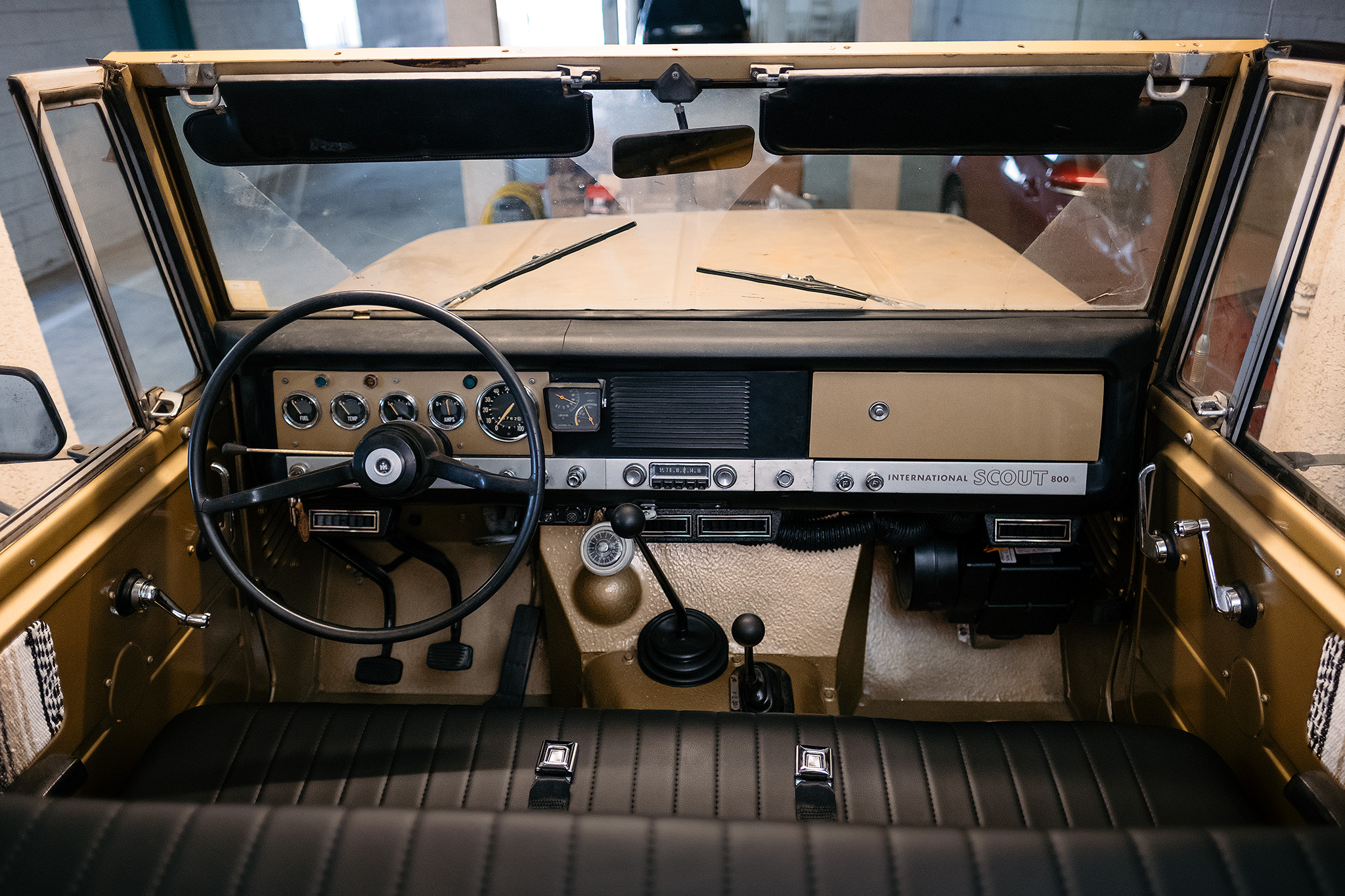
International Harvester Scout 800a
Old Air Products AC Install
I hate the heat. So does our dog with his thick winter coat. Scout’s also run hot. My overall goal when building our Scout (1970 IH Scout 800a with a 304e engine) was to make it a little easier to drive and a little more comfortable on the day to day. One thing I knew I wanted from the beginning was AC.
There are no AC kits specific to the Scout 800’s. I got onto Vintage Air who gave me the number of a shop they recommended for doing the AC install on the 800’s. I called them and they said it’s very involved and either requires pushing the dash further back or the firewall further forward. The rough estimate from them was somewhere between 5 and 10k. It might have been around 8k but I can’t remember exactly.
I had previously come across a writeup on Binder Planet by George Womack on his Old Air Products install into an 800. It was a great guide, but I thought I would expand on that write up a little with my experiences, particularly the moving of the drain plug which proved quite problematic for me, even if my final solution is easy enough.
This will by no means be a complete step by step guide, but hopefully might shed some light onto the process if you are looking to tackle it yourself.

PARTS LIST
Rough list of parts needed:
Old Air Products Kit
There appears to be 2 kits from Old Air Products (OAP) that MAY fit a Scout 800. I ordered the Hurricane 1000 Complete Kit which has the hoses coming from the evaporator towards the top of the unit (Image A). The 3000 appears to be the same evaporator unit but with the hoses closer to the bottom of the unit (Image B). Taking into account the position of these hoses on the evaporator, combined with your mounting position on the firewall, one position may be ideal over the other for your setup. More on this later.

My order form:

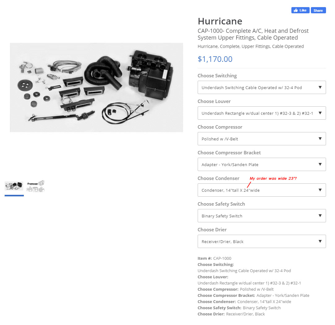
You may be able to use different items such as vents etc. but the order form above shows the ones I went with.
I went for the under dash rectangle louvers. I picked the 2 single side vents with a dual center vent. My order form above indicates I have a 14 x 23 inch condenser, but I could only see a 14×24 inch at the time of writing this article. I’m not sure which is right but you should also measure the space you have in front of your radiator as well. I got the York to Sanden compressor adapter plate (this will be dependent on the compressor bracket you find for your setup).
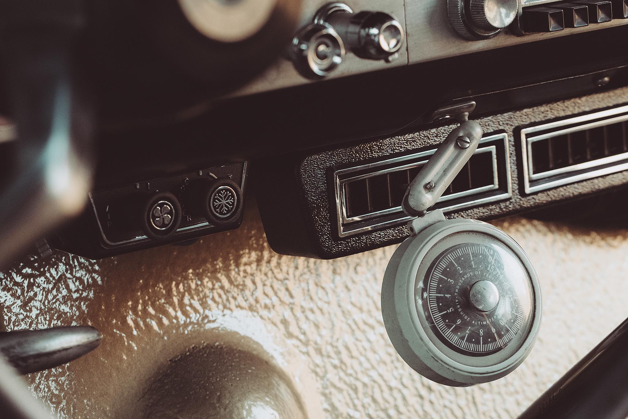
The other option to choose is mechanical controls (the OAP Hurricane 1000 or 3000) or electronic controls (OAP Hurricane 1100 or 3100). I went with mechanical cable for the defrost and heater controls. This works in the same way as the original heater/fan cable, with a pull knob and cable. These are slightly harder to mount as you need to run the stiff cable. In my situation, the defrost cable is looped around quite tightly from the dash down to the evaporator.
The cable controls feel more period correct to me, but the electronic controlled versions may be easier to mount and control.
I used the original Scout fan cable for the new heat lever control, and sourced a spare used fan cable to mount the new defrost cable control. I didn’t use the cables provided in the kit as these original parts retained the original pull knobs on the dash. I positioned the defrost cable on the dash next to the original fan knob. The good news is there should be a hole already cut in the steel of the dash for the extra cable, you will just have to cut the aluminium fascia (well at least that was the case on my Scout). If you feel from the inside of the dash to the right of the original heater knob, you should feel the hole already cut in the steel dash frame. Just center and drill the aluminium plate and you should be good to go.
You can see the original fan cables now used for heat and defrost in the following image:

Center plates to be laser etched for the pull knobs:

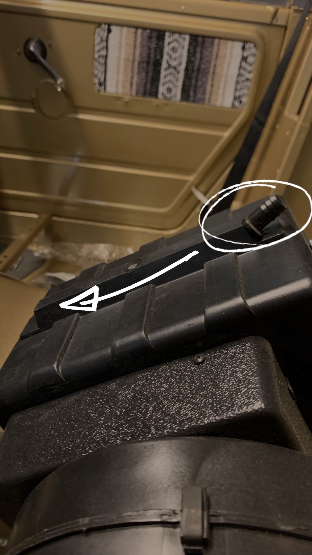
The Problematic Evaporator Drain Plug
From George’s writeup on Binder Planet:
“The other modification involves the drain fitting. It is installed at the bottom front of the evaporator case, but in this application it needs to be at the rear to be at the lowest point. OAP can install the drain fitting in the proper location if you specify this when ordering. If you do this yourself, be extremely careful when drilling the hole for the fitting so you don’t drill into the evaporator core! The duct hoses exit the evaporator right where the glovebox normally sits. I chose to just leave out the glovebox on this Scout, but it would also be possible to make a smaller glovebox if desired.”
This little drain plug was the biggest issue I had when trying to install the AC. Basically the Scout firewall leans toward the back of the car. The OAP evaporator is made for a firewall that leans toward the front of the car. This would mean the drain plug would not be at the lowest part of the case and therefore, water would pool. The fix sounds easy, just move the bung to the other end of the case, but this is harder than it sounds, well at least harder to do right.
George mentions having OAP fit the bung when ordering but when I called them and asked they said they couldn’t do that and seem surprised at the suggestion.
Next, I tried to find a shop that would weld plastic but that proved quite difficult. I decided I was going to try and weld it myself. The next problem I ran into was that the evaporator box is made out of ABS plastic. I could not find any 1/2 fittings made from ABS plastic. Most bungs that you come across in that size are PVC garden fittings. I don’t know much about plastic welding but apparently you do need to match plastics for it to work. After scouring the internet trying to find the correct size ABS bung, and failing, I ended up settling for what I read was one the strongest multi plastic adhesives you could use, M ScotchWeld DP420 Black Epoxy Adhesive.
In hindsight I should have also used a gusset to further strengthen the join but it has held up so far.
One option may be to 3d print a bung as I believe ABS plastic can be 3d printed, but I think there may be issues welding 3d parts too, so do your research.
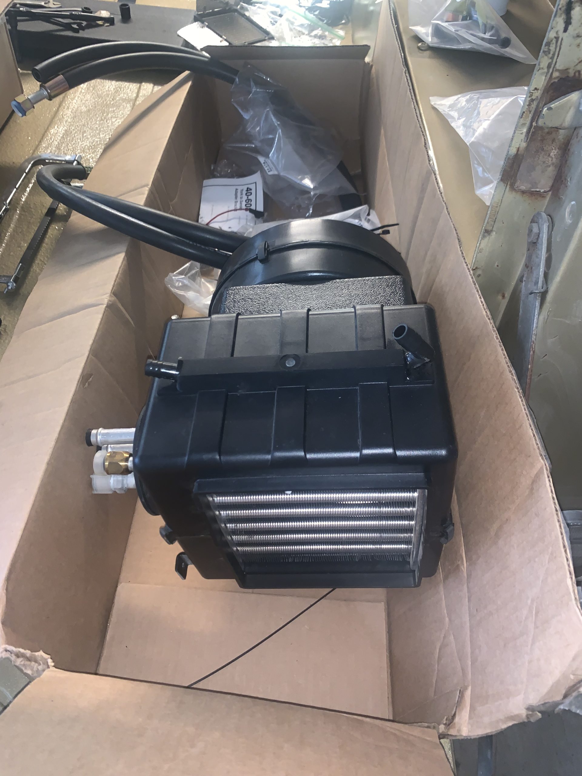
Evaporator Position/Location
The evaporator bolts to the firewall in the passenger foot well. I have positioned mine low to retain the glove box and clear the battery tray that I had relocated in the engine bay (see Image C). I had to make sure I lowered the evaporator enough for the hoses to clear that tray. In hindsight I should have purchased the OAP Hurricane 3000 kit with the hoses lower on the unit so I could have tucked the evaporator up higher under the dash. But I didn’t know about the hose position differences when I ordered mine.
I’m not sure how high you can place the evaporator without fouling on parts of the dash, but it can definitely go higher than mine so long as you don’t mind losing the glove box and don’t have anything interfering on the engine bay side (this should be clear having removed the original heater box anyway). Losing the glovebox would also make running/hiding the ducting easier as well as give you better access to the top of the evaporator unit once everything is installed (depending on how high you mount it).
Obviously, trial fit everything before cutting.
As the evaporator is low in my install, it would be easy for a passenger, or anything on the floor, to roll and knock the new, fragile drain bung. I made a guard out of some aluminium to bolt to the floor to protect it. There is still plenty of room for the passenger’s feet as the old seats have you sitting pretty square anyway. If you have tucked the evaporator up behind the dash you may not need to protect the drain as much.
The holes in the firewall from the old heater box should be welded up to make way for the new hole for the bulkhead.
The evaporator bracket can also do with being beefed up a bit. The supplied bracket is quite flimsy and on trial fitting, the evaporator unit wobbled around a lot. We bent up a new bracket out of 1/4″ flat bar in the exact same shape as the original.
The fresh air lever on the passenger side may also need to be trimmed to fit everything in.
Evaporator mounting considerations. You will not have the battery bracket to contend with, I moved mine here to make way for the vacuum brake upgrade:

Original firewall heater box hole welded up and hole cut for new AC bulkhead:

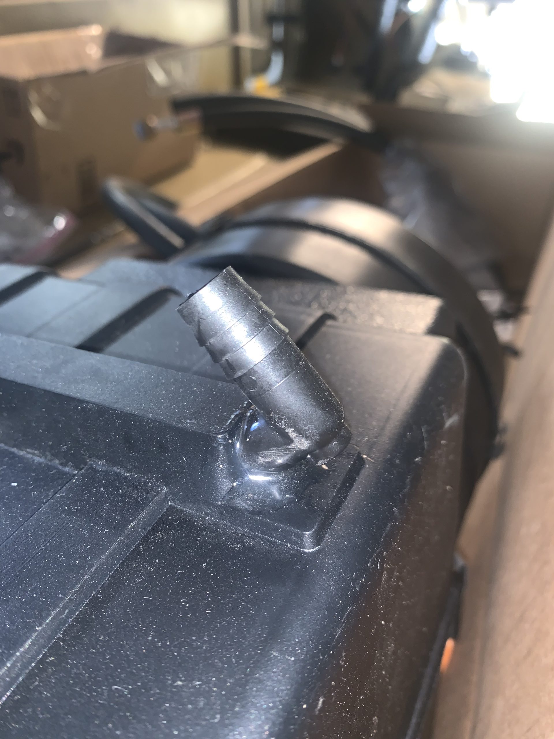
Gluing evaporator drain plug, mounting on firewall and drilling drain hole:
Hoses coming through the bulkhead into the engine bay:

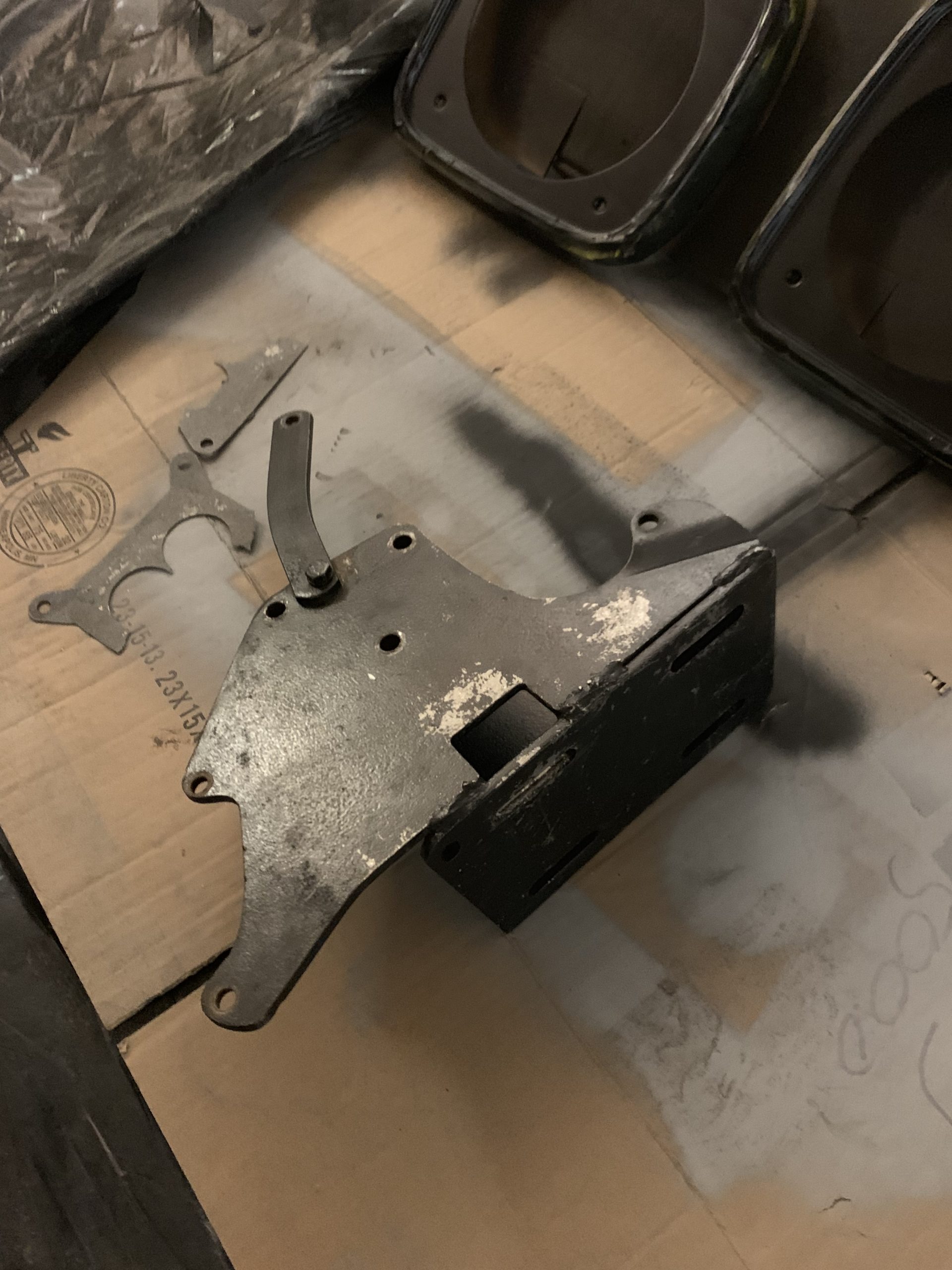
Condenser, Dryer & Compressor Bracket
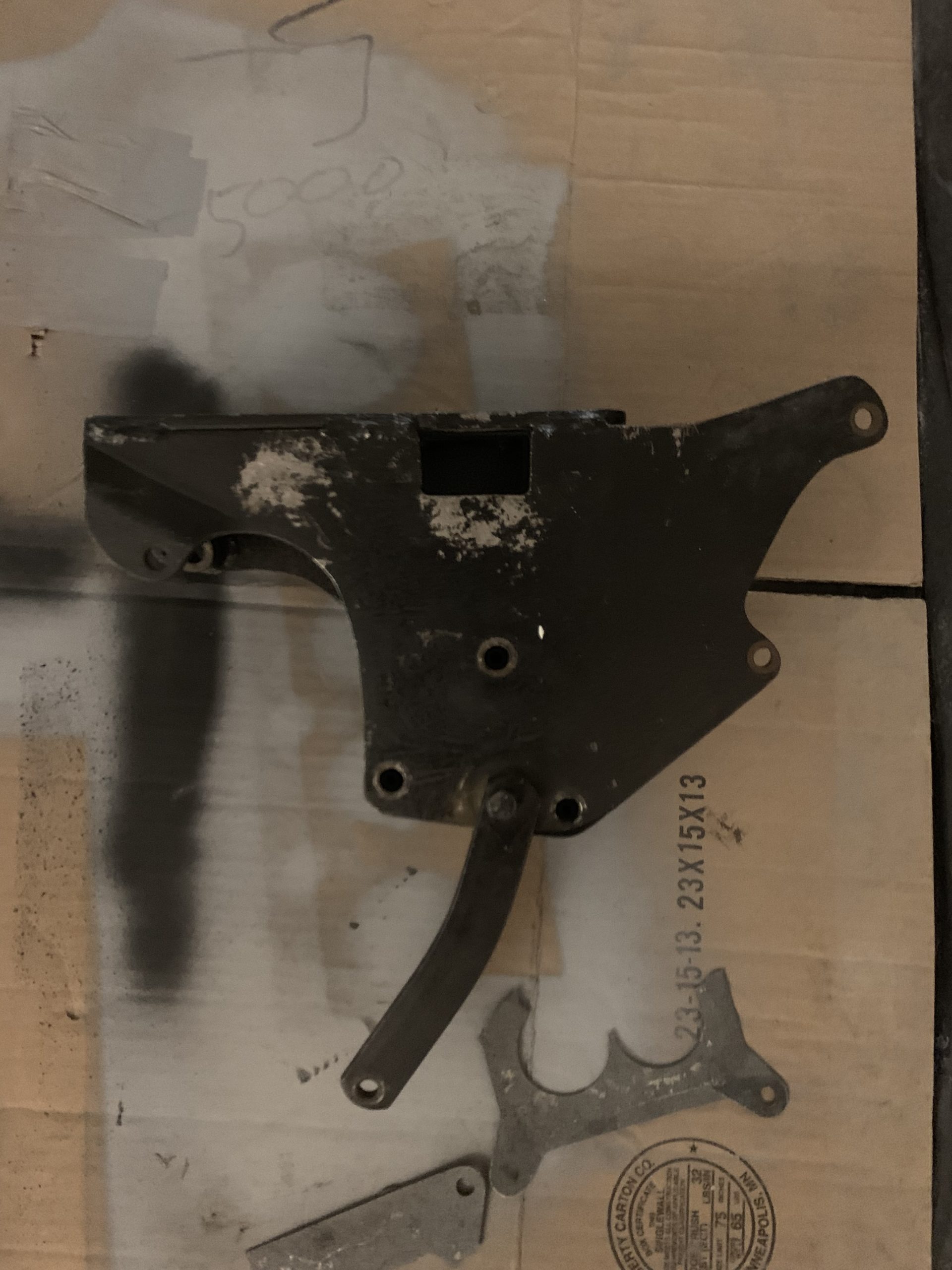
I found someone on the Scout groups on Facebook who had a compressor bracket and wanted to convert their 304 back to the original alternator setup. So I swapped my original alternator bracket for his AC bracket.
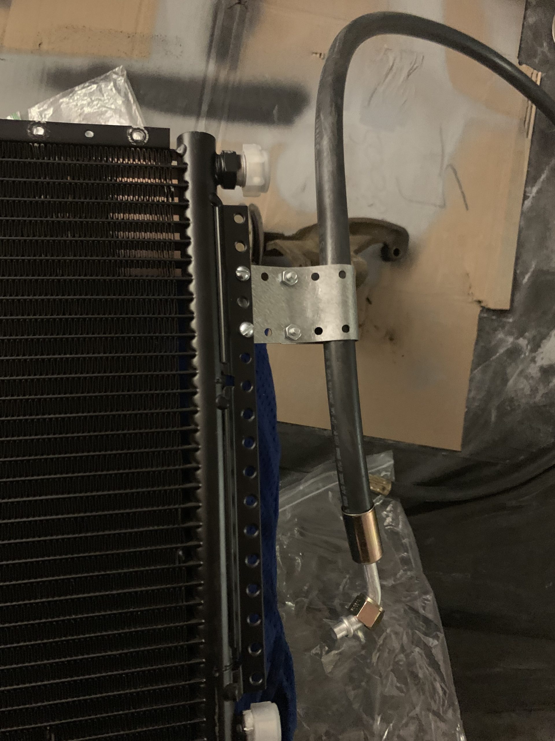
According to my order form I have a 14″ tall x 23″ wide condenser that fits perfectly in front of my (presumably) stock radiator. The larger condenser you can fit, the better cooling you will get. I had to remove the cross supports/bars as they now wouldn’t fit, but perhaps the extra rigidity from mounting the condenser would make up for this. Some of the steel plate provided for mounting was bent into a loop to run the hoses up the side of the condenser. Fuel hose/plastic covers from hose clamps were used to protect the hoses around edges.
The dryer was mounted behind the passenger headlight near the fresh air duct.
With everything in place, measure out the hoses and take them to a shop to be crimped (unless you have a crimping tool). Note the instructions recommend looping the hose to allow for flex/vibrations/movement, rather than running straight and tight hose.
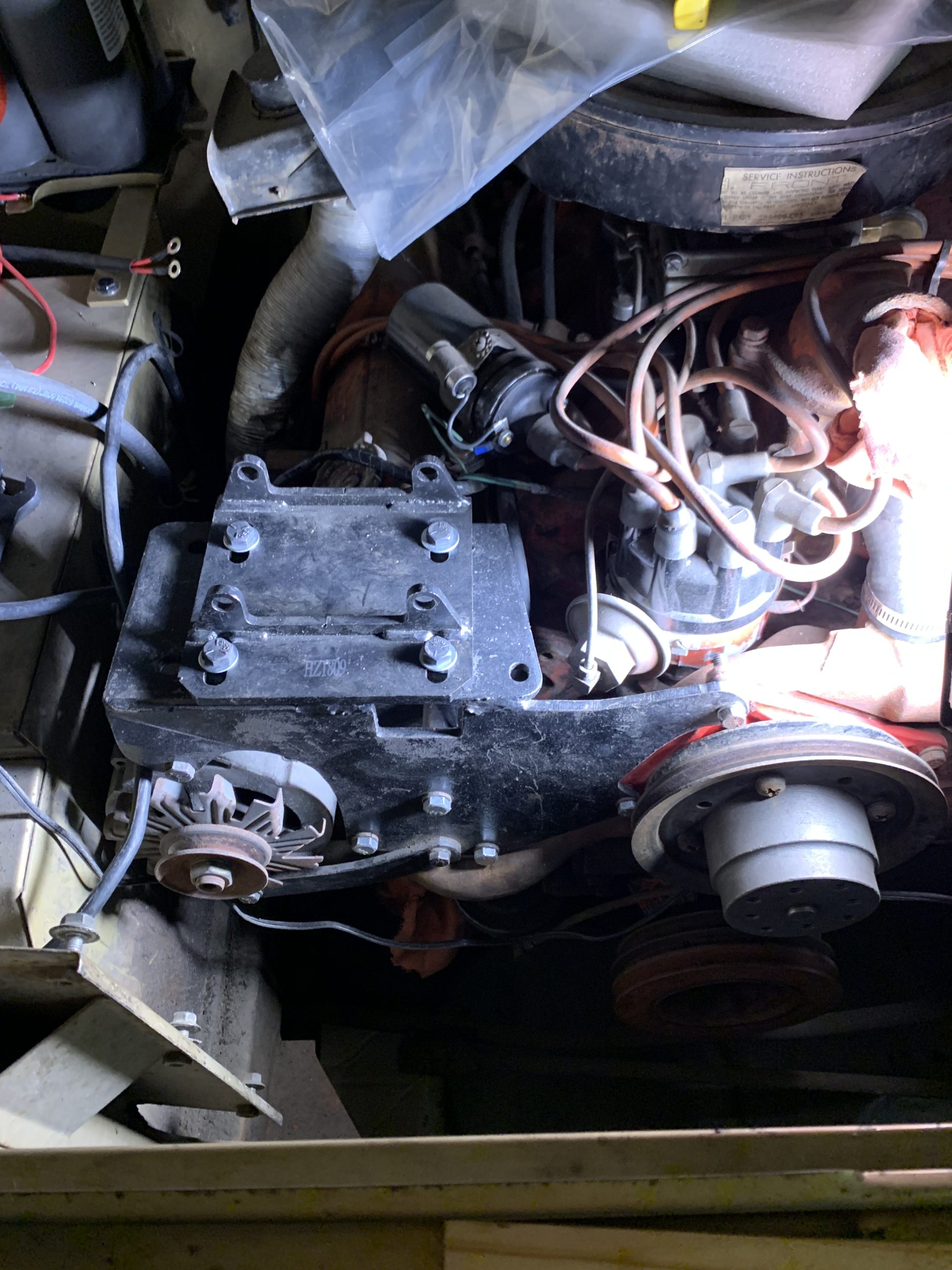
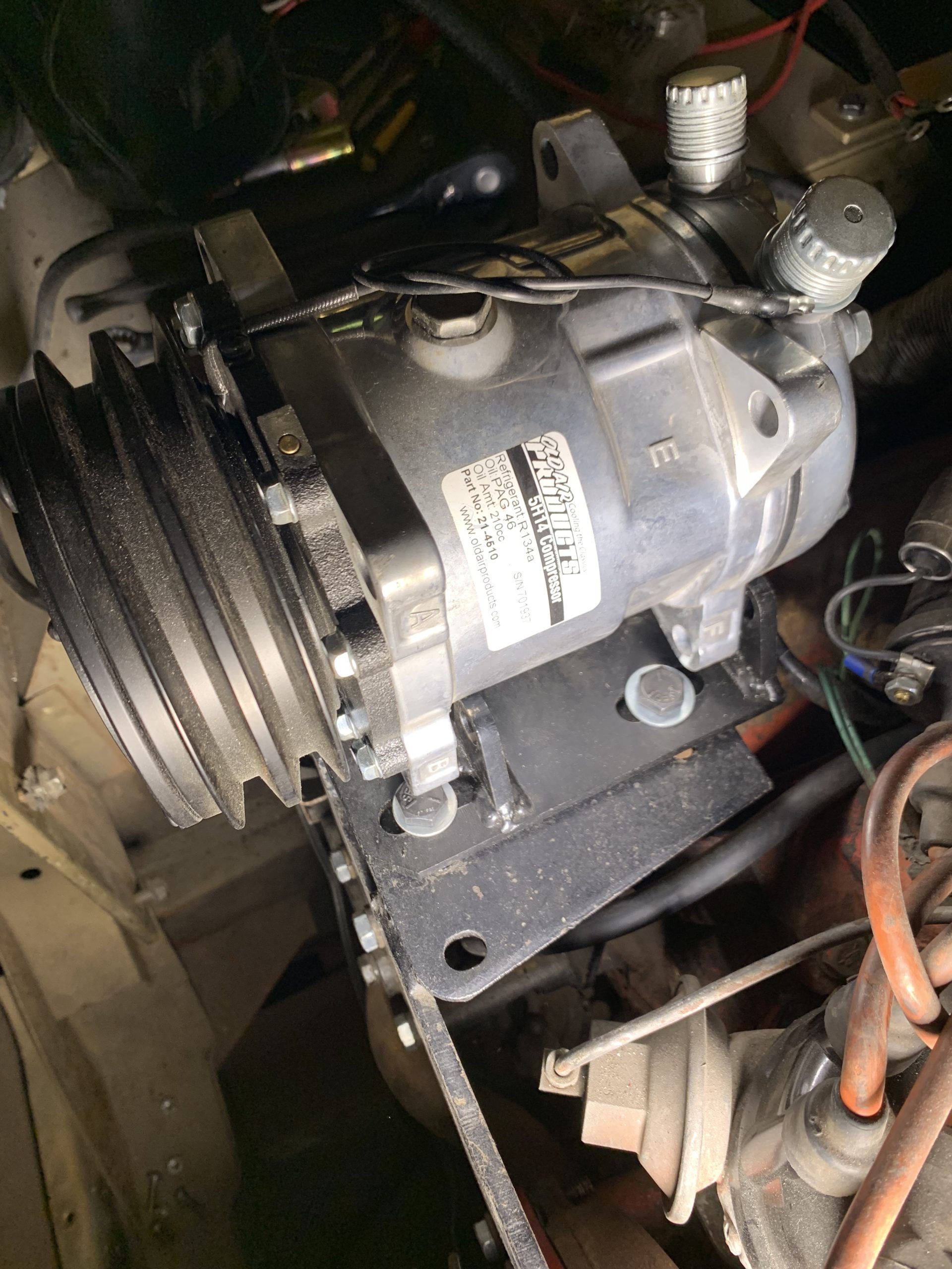
Depending on the style of bracket you have sourced/made, the tension on the alternator compressor belt will now most likely come from sliding the compressor laterally. This seems to have less room for adjustment (well at least in my setup) and you will need to make sure you have the appropriate length fan belt to go around the new components.
A 6 blade cooling fan should be installed to pull the extra air needed to cool the condenser/radiator. Make sure you are also running a shroud around the fan.
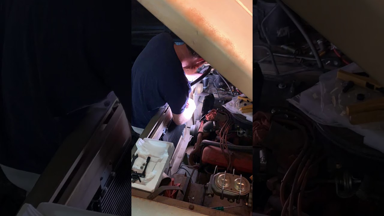
Condenser mounting:

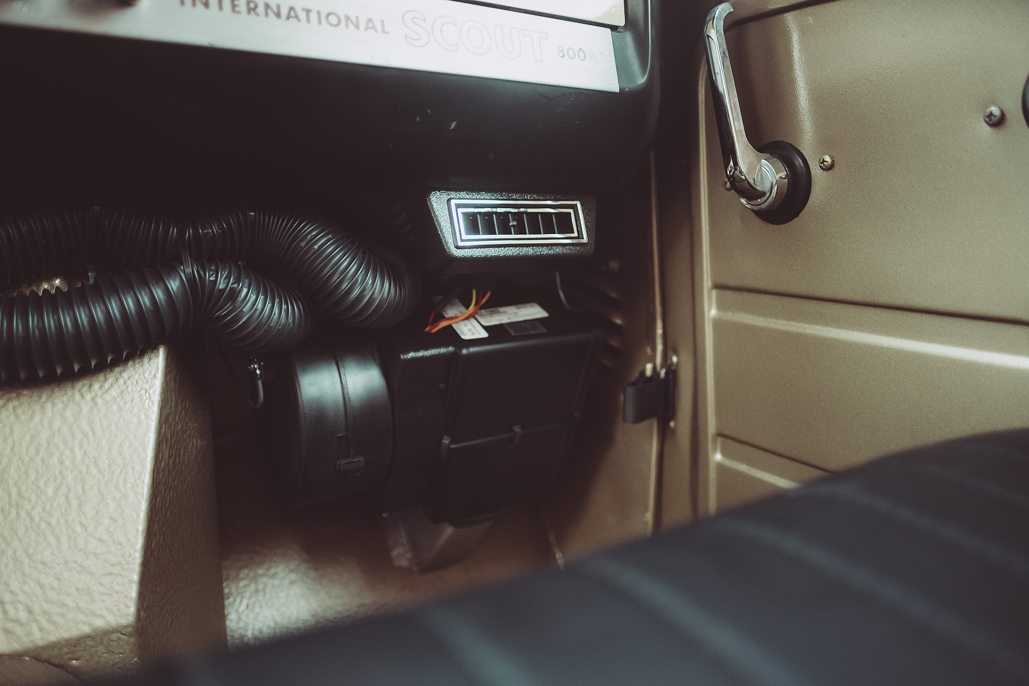
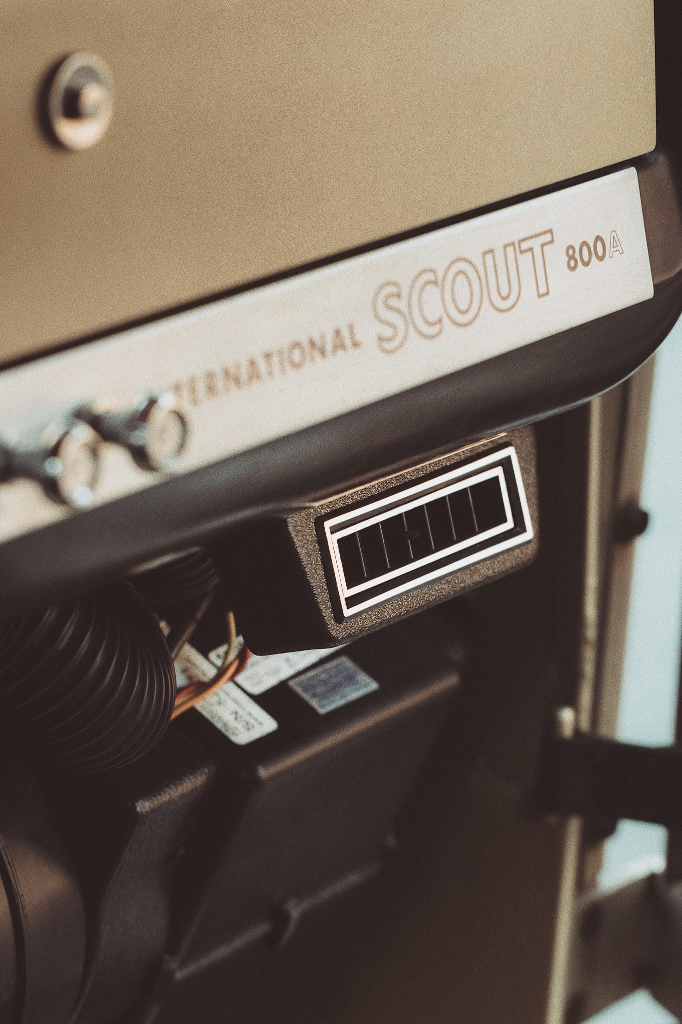
Vents
I mounted the vents flush with the inner lip under the dash. I used 1/4″ rubber as a spacer so that the vent is not tucked up/obscured by the dash as much.
I centred the dual vent under the radio in the middle of the dash with the under dash control panel just off to the drivers side and the single vents on the outer edges of the dash.
The vents have plastic tabs to secure the 2 inch hose fairly well. I used hose clamps to secure the defrost ducts to the fitting already on the dash/car.
I ran the ducting from the drivers side, behind the dash and above the radio, same as the defrost ducts. The passenger side is a very short duct to the evaporator and the centre ducts tucked just below the dash. This may be easier to run if you aren’t running the original radio and/or glove box, but I have both and made them fit.

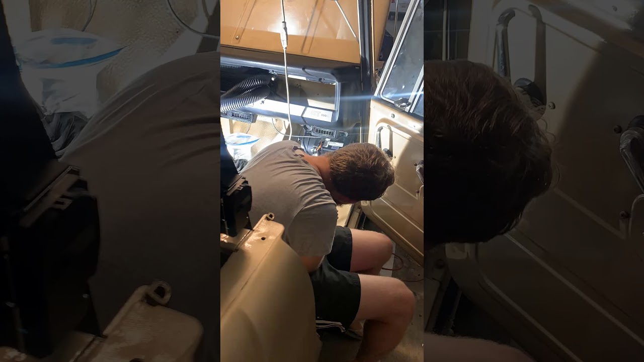
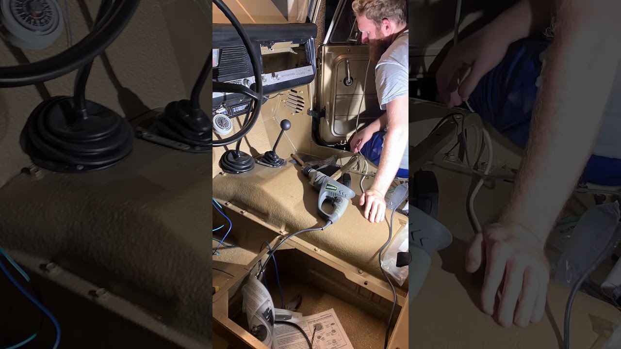
Timelapse fitting underdash vents and controls:
Wiring
Wiring is fairly straight forward and can be tucked behind the dash easy enough. I have the ignition wire running off a relay to take some load out of the main harness. Note that a supplied temperature wire/probe has to go from the control unit to the evaporator, so you need to position them close enough for that to reach.
Holley Sniper
The Holley Sniper has a sensor wire to allow kick-down when the compressor turns on. I am yet to wire this in but it still runs smoothly without it.
Gas
I think the manual recommends 28-32 pounds or refrigerant, but it all depends on the length of hoses used etc. so it might take some trial and error from the shop.
NOTES
My fan exploded in the first few months of use. Not sure exactly what happened but there was a loud pop and most of the fins on the hamster cage ripped off. OAP replaced the fan for me but I had to reinstall the fan. With the unit being tucked up and gassed up, I couldn’t really get to it properly to reseal the fan box so I have a pretty substantial air leak on the evaporator atm.
You may want to minimise as much heat as possible getting into the cabin as this will negate any cooling effect the AC has. I have lined my floors with Lizard Skin ceramic coating when I repainted. Dynamat or a similar product would probably work even better. I also wrapped the exhaust under the floors which made a massive difference to the temps inside. In the future I plan on lining the outside of the transmission tunnel and firewall with an aluminium heat shield too.
Cable controls feel more period correct, electric controls may function better and be easier to install. You need to decide which you will use when you order the AC kit.
The benefit of the AC system is not just the cooling but having the defrost plumbed into the AC to remove condensation when it’s humid.
The compressor bracket takes up a fair bit of room in the engine bay and may restrict access to the alternator and distributor etc.